
A first simulation
This example computes the reflection gain of a current-pumped Josephson parametric amplifier (JPA). It needs only JosephsonCircuits; plotting is optional. For installation, see the home page.
Build the circuit
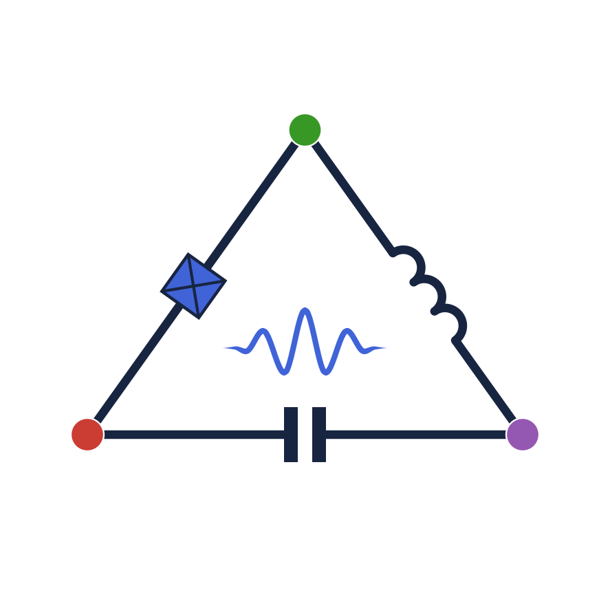
The port owns a matched 50 Ω termination. A coupling capacitor connects it to a junction shunted by a capacitor. Node 0 is ground; node 2 is the junction node.
 1                  2
 o------[cc]--------o--------+
 |                  |        |
[p1]              [jj]     [cj]
 |                  |        |
 o------------------o--------+
0using JosephsonCircuits
circuit = Circuit([
(:p1, 1, 0, Port(1; Z0 = 50.0)),
(:cc, 1, 2, Capacitor(100e-15)),
(:jj, 2, 0, JosephsonJunction(1000e-12)),
(:cj, 2, 0, Capacitor(1000e-15)),
])JosephsonJunction(Lj) takes the small-signal junction inductance in henries. A port already supplies its termination; adding a resistor across it adds another physical load. See ports.
Solve the pump and sweep the signal
Frequencies passed to harmonic balance are angular frequencies in rad/s. The pump's current is a Fourier coefficient in amperes: a real value Icoeff represents a cosine of peak current 2Icoeff.
fp = 4.75001e9                       # pump frequency, Hz
Icoeff = 0.00565e-6                  # pump Fourier coefficient, A
ws = 2pi .* (4.5:0.01:5.0) .* 1e9   # signal angular frequencies, rad/s
wp = (2pi*fp,)                      # one independent pump
sources = [(mode = (1,), port = 1, current = Icoeff)]

sol = hbsolve(ws, wp, sources, (8,), (16,), circuit)
@assert sol.nonlinear.solverinfo.converged
S11 = sol.linearized.S(outputmode = (0,), outputport = 1,
    inputmode = (0,), inputport = 1, freqindex = :)
gain_dB = 10 .* log10.(abs2.(S11))
round(maximum(gain_dB); digits = 1)13.3The gain peaks near the pump frequency. Here the input and output frequencies are equal, so photon gain and power gain coincide. (8,) sets the retained modulation harmonics for the signal calculation; (16,) sets the retained harmonics of the strong pump. These are numerical resolution choices, not device parameters.
Convergence of the nonlinear solver checks its residual on this grid. Before using the result quantitatively, increase the pump and modulation harmonic limits and compare the gain. Refine the nonlinear evaluation grid separately if necessary. See convergence.
Check against a closed form
With the pump off the circuit is linear: the junction is an inductance of 1 nH, and the port sees Z = 1/(iωCc) + 1/(iωCj + 1/(iωLj)), which reflects (Z - 50)/(Z + 50). The linear solve gives the same. Z is real at the resonance 1/(2π sqrt(Lj (Cc + Cj))), 4.80 GHz; the pump sits just below it.
off = hblinsolve(ws, circuit)
S11off = off.S(outputmode = (0,), outputport = 1, inputmode = (0,),
    inputport = 1, freqindex = :)
Z(w) = 1/(im*w*100e-15) + 1/(im*w*1000e-15 + 1/(im*w*1000e-12))
closed = [(Z(w) - 50)/(Z(w) + 50) for w in ws]
@assert isapprox(S11off, closed; atol = 1e-12)
(difference = maximum(abs.(S11off .- closed)),
    resonance = 1/(2pi*sqrt(1000e-12*(100e-15 + 1000e-15))))
(difference = 3.612065865298817e-14, resonance = 4.798702088783482e9)To plot the result, install Plots and continue in the same session:
using Plots
plot(ws ./ (2pi*1e9), gain_dB; xlabel = "Signal frequency (GHz)",
    ylabel = "Reflection gain (dB)", label = "JPA")
Apply the same pump in time
A TransientSource returns instantaneous current, so the waveform includes the factor of two. The smooth ramp starts the circuit at rest.
ramp(t) = t <= 0 ? 0.0 : t >= 2e-9 ? 1.0 : (1 - cospi(t/2e-9))/2
pump(Icoeff, fp) = t -> 2Icoeff*ramp(t)*cospi(2fp*t)
problem = transientproblem(circuit; sources = [TransientSource(1, pump(Icoeff, fp))])
solution = transientsolve(problem, (0.0, 5e-9); dt = 2.5e-12)
(size(solution.voltage, 1), first(solution.times), last(solution.times))
(1, 0.0, 5.0e-9)The voltage array has one row per port and one column per saved time. This short record illustrates turn-on; it is not a settled measurement of the frequency-domain gain. A transient gain calculation also needs a probe or a tangent response. Continue with the transient guide.
Choose the next analysis
| Question | Analysis |
|---|---|
| What is the steady pump response? | hbnlsolve |
| What weak signals and idlers does it amplify? | hblinsolve about that operating point, or hbsolve for both steps |
| Do perturbations about this state grow? | hbstability, after checking the operating point |
| How does a pulse propagate or deplete the pump? | transientsolve |
| What is the incremental response about a recorded trajectory? | transienttangent, transientadjoint, or transientgain |
| What noise is measured in a time window? | transientnoise with a temporal-mode plan |
See conventions for current amplitudes, signed modes, wave normalization, and the units of the returned states.